

The home automation circuit is built around an Arduino Uno board, Bluetooth module HC-05 and a 4-channel relay board. The number of channels depends on the number of appliances you wish to control. Arduino Uno is powered with a 12V DC adaptor/power source. The relay module and Bluetooth module can be, in turn, powered using a board power supply of Arduino Uno.
Circuit Diagram:
Here’s what you’ll need to get started:
- Arduino UNO R3
- Relay module
- HC 05 Wireless Bluetooth Module
- 12v DC Adaptor (power supply)
- 5v DC Fan
- 3 Bulb Holder
- 3 Led Bulb 4watt
- 12v 500mA Transformer (230V to 12V)
- 2.2k ohm resistor
- 1k ohm resistor
- Breadboard
- Jumper wires

- Arduino UNO R3
- Relay module
- HC 05 Wireless Bluetooth Module
- 12v DC Adaptor (power supply)
- 5v DC Fan
- 3 Bulb Holder
- 3 Led Bulb 4watt
- 12v 500mA Transformer (230V to 12V)
- 2.2k ohm resistor
- 1k ohm resistor
- Breadboard
- Jumper wires
How to Connect the Bluetooth HC-05 to the Arduino:
1) Connect the Arduino’s +5V and GND pins to the bus strips on the breadboard, as shown in the above circuit diagram.
2) Power the HC-05 module by connecting the 5V and GND pins to the bus strips on the breadboard. The HC-05 is powered using 5VDC but includes an on-board voltage regulator that generates a 3.3V supply to power the transceiver. This means the TXD/RXD pins operate at only 3.3V.
3) Connect the TXD pin on the HC-05 module with the RXD pin (Pin 0) on the Arduino. This connection allows the HC-05 to send data to the Arduino. The reason why we pair up TXD on the bluetooth module with RXD on the Arduino is simple. The TXD pin is used to transmit data from the bluetooth transceiver, while the RXD pin is used to receive data on the Arduino.
Although the Arduino is using 5V signal levels, and the HC-05 is using only 3.3V signal levels, no level shifting is required on this particular signal. This is because the Arduino is based on an Atmel ATmega328 microcontroller which defines a logic high as any level above 3V. So no level shifting is necessary when going from 3.3V to 5V. However, that isn’t always true when going the other direction from 5V to 3,3V as we’ll discuss in the next step.
4) Now we need to connect the TXD pin on the Arduino to the RXD pin on the HC-05. This connection will form the second half of the two-way communication and is how the Arduino sends information to the HC-05.

Since the receiver data lines on the HC-05 are only 3.3V tolerant, we need to convert the 5V transmit signal coming from the Arduino into a 3.3V signal. While this is usually best done using a logic level converter, we’re instead just using a simple voltage divider to convert the 5V signal into a 3.3V signal.
We’ve connected a 1k ohm and a 2.2k ohm resistor across the GND and TXD pins on the Arduino. This is called a resistor divider because it divides down the input voltage. We obtain the 3.3V level signal from the intersection of these two resistors.
The equation for a divided down voltage is Vout = [2.2k/(2.2k + 1k)]*5V = (2.2k/3.2k)*5V = 3.46V, which is close enough to 3.3V to prevent any damage to the HC-05.
This crude solution should never be used with a high-speed signal because the resistors form a low-pass RC filter with any parasitic capacitance on the connection.
Once you have connected the HC-05 module to the Arduino, you can power the Arduino with a 12V DC supply or USB cable. If the red and blue LEDs on the HC-05 are blinking, then you have successfully connected the bluetooth module with the Arduino.
We don’t use the STATE and EN pins on the HC-05 module, since they are not required for this setup.
Setting up the Relay Circuit:

Here’s how to connect the
relay module to the Arduino:
1) First, connect the 5V and GND pins of
the relay module to the bus terminals on the breadboard.
2) Next, connect the input pin on the relay
module with PIN 2, 3, 4, 5 on the Arduino.
3) Now we need to connect the AC load to
the relay module. If you look carefully at the terminal block on the relay
module, you’ll find these three terminals:
Here’s how the relay module works:
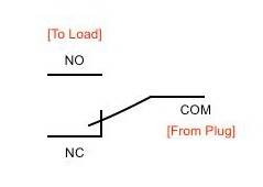
When the relay is off, the COM terminal is connected to the NC
(Normally Closed) terminal, which means if you connect the bulb to the NC
terminal, it will turn ON even when the relay isn’t energized. But that’s not
what we want.
We want to turn on the bulb only when we
send a signal from smartphone. That’s the reason we connect the load to the NO
(Normally Open) terminal, so that when the relay is triggered from the Arduino,
the contact switches from the NC terminal to the NO terminal, thereby
completing the circuit.
CAUTION: The relay module we’re
using can handle up to 10 amps of current at up to 240V AC. That’s enough
current for a lot of devices but not enough for high power appliances like
a heater or dryer. For high power appliances you’ll likely need about
twice the current capacity (~ 20 amps). You can either upgrade to a
higher current relay, or place multiple relays in parallel. Two 10 amp
relays in parallel are equivalent to a single 20 amp relay since half of the current
goes through each relay.
Android apk can be downloaded from Here!
Code:
//using ports 2, 3, 4, 5
int relay1 = 2;
int relay2 = 3;
int relay3 = 4;
int relay4 = 5;
int val;

void setup() {

  Serial.begin(9600);
  pinMode(relay1,OUTPUT);
  pinMode(relay2,OUTPUT);
  pinMode(relay3,OUTPUT);
  pinMode(relay4,OUTPUT);
  digitalWrite(relay1,HIGH);
  digitalWrite(relay2,HIGH);
  digitalWrite(relay3,HIGH);
  digitalWrite(relay4,HIGH);

}
void loop() {

  //check data serial from bluetooth android App
  while (Serial.available() > 0){
    val = Serial.read();
    Serial.println(val);
  }

  //Relay is on
  if( val == 1 ) {
    digitalWrite(relay1,HIGH); }
  else if( val == 2 ) {
    digitalWrite(relay2,HIGH); }  else if( val == 3 ) {
    digitalWrite(relay3,HIGH); }
  else if( val == 4 ) {
    digitalWrite(relay4,HIGH); }

  //relay all on
  else if( val == 0 ) {
    digitalWrite(relay1,HIGH);
    digitalWrite(relay2,HIGH);
    digitalWrite(relay3,HIGH);
    digitalWrite(relay4,HIGH);
  }
  //relay is off
  else if( val == 5 ) {
    digitalWrite(relay1,LOW); }
  else if( val == 6 ) {
    digitalWrite(relay2,LOW); }
  else if( val == 7 ) {
    digitalWrite(relay3,LOW); }
  else if( val == 8 ) {
    digitalWrite(relay4,LOW); }

  //relay all off
  else if( val == 10 ) {
    digitalWrite(relay1,LOW);
    digitalWrite(relay2,LOW);
    digitalWrite(relay3,LOW);
    digitalWrite(relay4,LOW);
  }
}

0 Comments