
In a hospital health care monitoring system it is necessary to constantly monitor the patient’s physiological parameters.
As the goal of this project, we see a device that can detect ailments in a patient and inform them to the concerned medical doctor’s team, without the intervention of even the patient himself. This process is done with three parts of the system, Heartbeat and temperature sensor, transmitter, and receiver.

Block Diagram:

Here’s what you’ll need to get started:
- Arduino uno board
- ECG AD8232 Sensor
- Heart beat sensor
- Temperature sensor(LM35)
- GSM sim900A
- 16*2 LCD Display
- Glucose indicator(by using ultrasonic sensor)
- Transformer
- Pc/Laptop
- Bread board
- Jumper wires
LM35 Temperature Sensor:


Pulse Sensor:
The Pulse Sensor is a plug-and-play heart-rate sensor for Arduino. It can be used by students, artists, athletes, makers, and game & mobile developers who want to easily incorporate live heart-rate data into their projects. The essence is an integrated optical amplifying circuit and noise eliminating circuit sensor. Clip the Pulse Sensor to your earlobe or fingertip and plug it into your Arduino, you can ready to read heart rate. Also, it has an Arduino demo code that makes it easy to use.
The pulse sensor has three pins: VCC, GND &
Analog Pin.

There is also a LED in the center of this sensor module which helps in detecting the heartbeat. Below the LED, there is a noise elimination circuitry that is supposed to keep away the noise from affecting the readings.

ECG AD8232 Sensor:
The AD8232 Single Lead Heart Rate Monitor is used to measure the electrical activity of the heart. This electrical activity can be charted as an ECG or Electrocardiogram and output as an analog reading.

ECGs can be extremely noisy, the AD8232 Single Lead Heart Rate Monitor acts as an op amp to help obtain a clear signal from the PR and QT Intervals easily. The AD8232 is an integrated signal conditioning block for ECG and other biopotential measurement applications. It is designed to extract, amplify, and filter small biopotential signals in the presence of noisy conditions, such as those created by motion or remote electrode placement.
The AD8232 Heart Rate Monitor breaks out nine connections from the IC that you can solder pins, wires, or other connectors to. SDN, LO+, LO-, OUTPUT, 3.3V, GND provide essential pins for operating this monitor with an Arduino or other development board. Also provided on this board are RA (Right Arm), LA (Left Arm), and RL (Right Leg) pins to attach and use your own custom sensors. Additionally, there is an LED indicator light that will pulsate to the rhythm of a heart beat.

Ultrasonic Sensor HC-SR04:
Ultrasonic Sensor HC-SR04 is a sensor that can measure distance. It emits an ultrasound at 40 000 Hz (40kHz) which travels through the air and if there is an object or obstacle on its path It will bounce back to the module. Considering the travel time and the speed of the sound you can calculate the distance.

The configuration pin of HC-SR04 is VCC (1), TRIG (2), ECHO (3), and GND (4). The supply voltage of VCC is +5V and you can attach TRIG and ECHO pin to any Digital I/O in your Arduino Board.

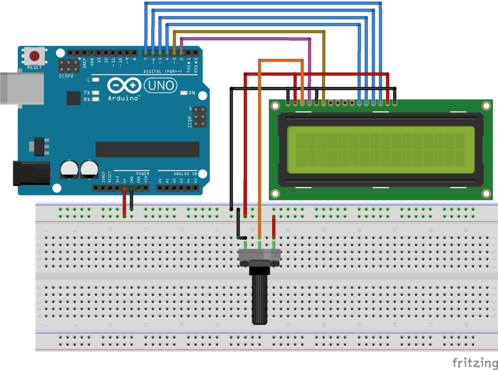
16*2 LCD:
LCDs (Liquid Crystal Displays) are used in embedded system applications for displaying various parameters and status of the system.

LCD 16x2 is a 16-pin device that has 2 rows that can accommodate 16 characters each.
LCD 16x2 can be used in 4-bit mode or 8-bit mode.It is also possible to create custom characters.It has 8 data lines and 3 control lines that can be used for control purposes.
Working of “Patient Monitoring System”:
A “PATIENT MONITORING SYSTEM” system is used Mainly three parts of the system, Heartbeat and temperature sensor, transmitter, and receiver. There are mainly two parts of the system one is a transmitter and the other one is the receive.
(a) Heart beat sensor is used
to measure heartbeat rate.
(b) The Temperature sensor is used to measure body temperature
In the transmitter, We have Heartbeat sensor and the temperature sensor. All the sensors are connected to the patient
The microcontroller monitors all the system in the transmitter if any abnormality in the patient condition then it sends the signal so that the receiver will capture the signal and will work according to that.
Patient monitoring has 3 sensors. First one is a body temperature sensor, second is Heartbeat sensor and the third one is the ECG module. This project is very useful since the doctor can monitor patient health parameters just by mobile And nowadays many IOT apps are also being developed. So now the doctor or family members can monitor or track the patient health through the Android apps.
ECG Output:


Project File can be downloaded from Here!
PPT can be downloaded from Here!
Code:
AD8232 Heart Rate sensor

void setup() {
  // initialize the serial communication:
  Serial.begin(9600);
  pinMode(2, INPUT); // Setup for leads off detection LO +
  pinMode(3, INPUT); // Setup for leads off detection LO -

}

void loop() {

  if((digitalRead(2) == 1)||(digitalRead(3) == 1)){
    Serial.println('!');
  }
  else{
    // send the value of analog input 2:
      Serial.println(analogRead(A0));
  }
  //Wait for a bit to keep serial data from saturating
  delay(1);

Ultrasonic, LM35, Bluetooth module, Heart rate sensor, LCD
//Bluetooth
#include <SoftwareSerial.h>
SoftwareSerial BTserial(10, 11); // RX | TX

// Ultrasonic
const int trigPin = 7;
const int echoPin = 6;
const int buzzer = 5;
const int led = 4;
long duration;
int distance;
int safetyDistance;


//LM35 temperature sensor
#define sensor A0
byte degree[8] =
{
  0b00011,
  0b00011,
  0b00000,
  0b00000,
  0b00000,
  0b00000,
  0b00000,
  0b00000
};

// LCD Display
#include <LiquidCrystal.h>
const int rs = 8, en = 9, d4 = 10, d5 = 11, d6 = 12, d7 = 13;
LiquidCrystal lcd(rs, en, d4, d5, d6, d7);

//The Pulse Sensor
#define USE_ARDUINO_INTERRUPTS true // Set-up low-level interrupts for most acurate BPM math
#include <PulseSensorPlayground.h>
const int PulseWire = 1; // PulseSensor PURPLE WIRE connected to ANALOG PIN 1
const int LED13 = 13; // The on-board Arduino LED, close to PIN 13.
int Threshold = 550; // Determine which Signal to "count as a beat" and which to ignore
PulseSensorPlayground pulseSensor;

void setup() {
  Serial.begin(9600); // begin serial communitication
  //Bluetooth
  BTserial.begin(9600);

//ultrasonic sensor
pinMode(trigPin, OUTPUT);
pinMode(echoPin, INPUT);
pinMode(buzzer, OUTPUT);
pinMode (led, OUTPUT);


//LCD Display
lcd.begin(16, 2);

//The Pulse Sensor
pulseSensor.analogInput(PulseWire);
pulseSensor.blinkOnPulse(LED13); //auto-magically blink Arduino's LED with heartbeat.
pulseSensor.setThreshold(Threshold);
if (pulseSensor.begin()) {
  Serial.println(" Initialising !"); //This prints one time at Arduino power-up, or on Arduino reset.
}
}

void loop() {
  //temperature sensor
  float reading = analogRead(sensor);
  float temperature = reading * (5.0 / 1023.0) * 100;
  delay(20);
   Serial.println("Wait"); //This prints one time at Arduino power-up, or on Arduino reset.

  //The Pulse Sensor
  int myBPM = pulseSensor.getBeatsPerMinute();
  if (pulseSensor.sawStartOfBeat()) {
    Serial.println(" HeartBeat found! "); // If test is "true", print a message "a heartbeat happened".
    Serial.print("BPM: "); // Print phrase "BPM: "
    Serial.println(myBPM); // Print the value inside of myBPM.
    lcd.setCursor(0, 0);          //sets the cursor at row 0 column 0
    lcd.print("Pulse:" + String(myBPM) + "BPM"); // prints 16x2 LCD MODULE
    Serial.print("Pulse:" + String(myBPM) + "BPM"); // prints 16x2 LCD MODULE
    lcd.setCursor(0, 1);          //sets the cursor at row 0 column 0
    lcd.print(String("Temp.: ") + temperature + ("C")); // prints 16x2 LCD MODULE
    Serial.print("Temp.: " + String(temperature)); // prints 16x2 LCD MODULE
    BTserial.print(String(myBPM) + "BPM");
  }
  delay(40); // considered best practice in a simple sketch.


   //ultrasonic sensor
    long duration, distance; // start the scan
    digitalWrite(trigPin, LOW);
    delayMicroseconds(20); // delays are required for a succesful sensor operation.
    digitalWrite(trigPin, HIGH);
    delayMicroseconds(10); //this delay is required as well!
    digitalWrite(trigPin, LOW);
    duration = pulseIn(echoPin, HIGH); //defining variables
    distance = (duration / 2) / 29.1; // convert the distance to centimeters.
    if (distance >= 8) {
      tone(buzzer, 1000, 500);
      digitalWrite(led, HIGH); // Turn the LED on
      Serial.println("ALERT! LOW GLUCOSE LEVELS DETECTED");
    }
    else {
      digitalWrite(led, LOW); // Keep the LED off
    }
  }

0 Comments